This project consisted of a new 6-story residential structure with a 16,000 SF footprint and one level of below-grade parking. The proposed building footprint was bordered by existing features, including a 3-story brick building directly to the east. The existing structure did not have a basement and was supported on shallow footings, including footings located directly along the property line. The cut height for the proposed basement level parking was about 15-20 feet from existing grades and within the bearing zone of the existing shallow footings. As such, the project required an excavation support system that was able to achieve the proposed cut heights and maintain support of the existing adjacent structure.
Geotechnical Conditions:
Subsurface soil conditions generally consisted of about 3 to 10 feet of fill and organics, overlying natural medium dense to dense sand and gravel. Groundwater was encountered approximately 7 to 10 feet below existing grades.
Excavation Support Solution:
The project team worked closely with HELICAL to consider several excavation support schemes and help maximize project efficiency. Four-sided and three-sided schemes were considered, and the team decided on a three-sided scheme with a sloped open cut along the western boundary. The three-sided scheme reduced the excavation support scope by over 30%. The design also included intermediate benching in some areas to reduce the effective cut height to ≤17 feet and eliminate the need for internal bracing. The final excavation support design included two different wall types:
- 350 linear feet of temporary Soldier-Pile-and-Lagging Wall was installed (see Photo 1 below). The soldier piles consisted of steel h-pile sections spaced at 6 to 8 feet on center and were driven into the ground with a vibratory hammer. The soldier piles were installed to a predetermined design tip elevation that varied from 25 to 35 feet below grade. Timber lagging boards were installed/stacked in maximum 5-foot lifts between the pile sections to form a continuous wall.
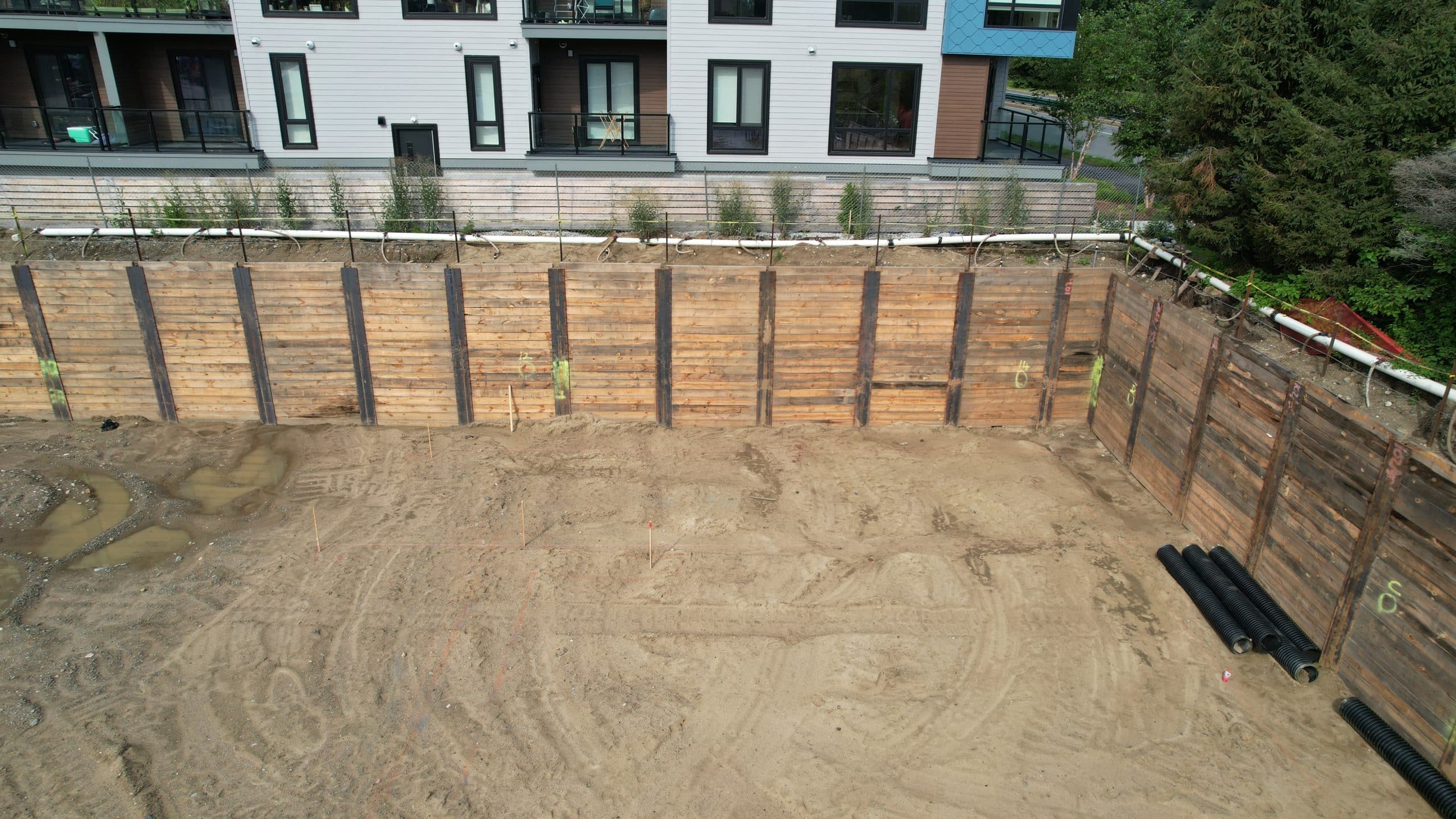
Soldier-Pile-and-Lagging Wall
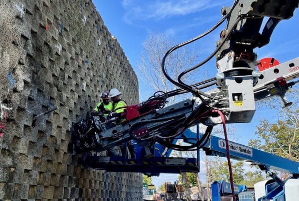
- Installing a soldier-pile-and-lagging wall directly adjacent to the abutting brick structure to the east was not possible due to vibration concerns during soldier pile installation and the risk of undermining the existing shallow footings during lagging installation (see Photo 2 below). 100 linear feet of permanent Secant Pile Wall was installed to provide general excavation support and shore the existing footings. Overlapping secant piles were installed within 6 inches of the footings (and within 1 foot of the building wall) using a non-vibratory, cased drilling system. Each secant pile consisted of a continuous 20-inch-diameter concrete shaft. Each alternating pile included a steel h-pile core for additional reinforcement. The secant piles were drilled to the designed tip elevation that was roughly 30 feet below grade.
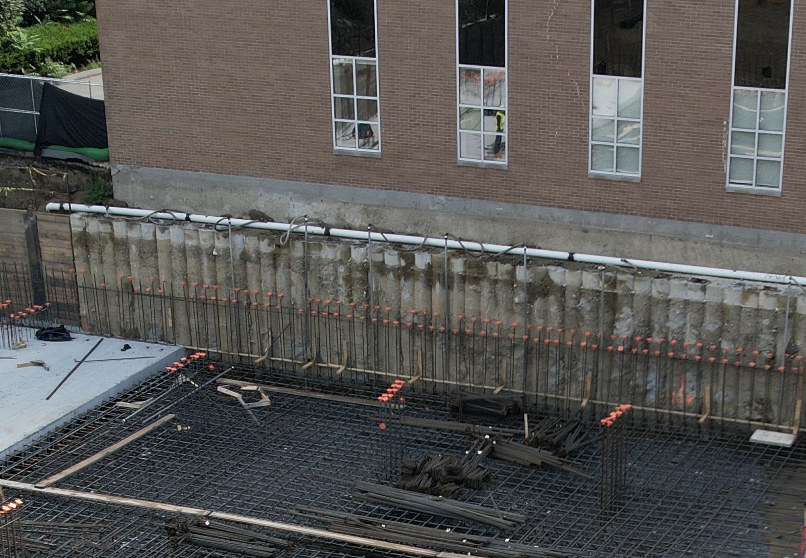
Secant Pile Wall Shoring the Adjacent Building