The focus of this month’s Brief is a “back-to-basics” ground improvement topic that underscores the fundamentals of proper field modulus testing of Geopier Rammed Aggregate Pier® systems. Note that this Brief only applies to non-rigid Aggregate Pier (AP) elements, not rigid inclusions. For further information on rigid inclusion testing, please refer to our April 2021 and August 2022 Briefs.
APs are high stiffness elements that work together with the surrounding “matrix” soils to create a reinforced soil mass with enhanced bearing capacity and settlement control. Although APs are highly effective at improving the surrounding matrix soils, their inherent higher stiffness attracts more of the footing load. Refer to Figure 1 below for an illustration of aggregate pier stiffness vs. matrix soil stiffness using a common “spring analogy” where the matrix soil stiffness is represented by a softer spring (km) and the AP stiffness is represented by a stiffer spring (kg).
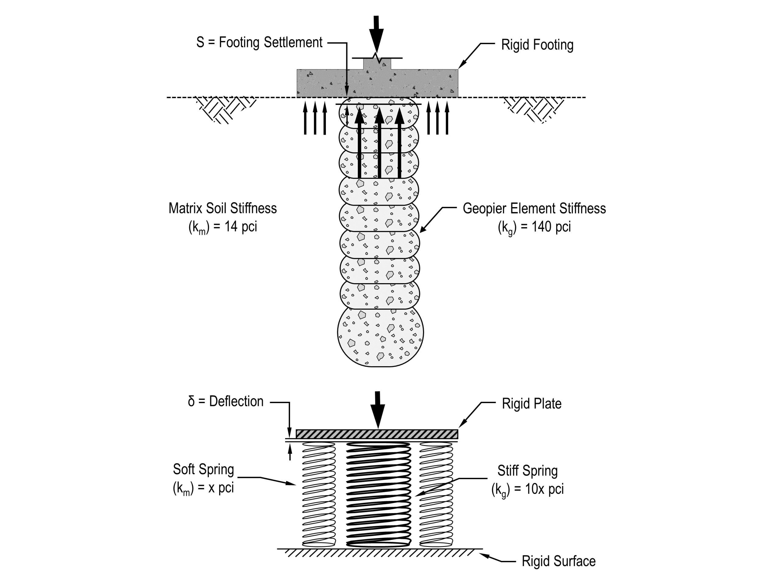
Figure 1 – Spring Analogy for a Footing Supported on Aggregate Piers (Source: Geopier Foundation Company Technical Bulletin 12)
In the Figure 1 example, the AP element is 10x stiffer than the surrounding matrix soil. Thus, for a footing designed for a bearing pressure of 5 kips per square foot (ksf), the stiff APs will attract a “top-of-pier stress” that exceeds the footing bearing pressure. In fact, pressure plate testing indicates that the stress on the top of the AP element is generally on the order of 2.5 to 3 times higher than the bottom of footing contact pressure! For this reason, field modulus testing should be a function of design top-of-pier stress, not design footing bearing pressure, to help demonstrate that the aggregate pier will exhibit a safe response during service loading. Now let’s take a closer look at why this is important based on modulus test results.
Standard local practice is to incrementally load the test element to a maximum load of 150% of the design top-of-pier stress. Alternate modulus testing methods that suggest that testing should be run to 150-200% of design footing bearing pressure are unconservative and inappropriate as illustrated with the following example.
With reference to Figure 2 below, let’s assume a design footing bearing pressure of 5 ksf and an associated top-of-pier stress of 16 ksf. Since local standard practice is to incrementally load the modulus test 150% of the top-of-pier stress, this would equate to a maximum test stress of 1.5 x 16 ksf = 24 ksf. Figure 2 plots the top-of-pier deflection (blue line) vs. top-of-pier stress. At the design top-of-pier stress of 16 ksf, the associated top-of-pier deflection is about 0.3 inches and represents how the AP is expected to deflect under service loading. At a top-of-pier stress that is equal to the footing design bearing pressure (5 ksf), the associated top-of-pier deflection is <0.1 inches and therefore underpredicts deflection by a factor greater than three. Even at a top-of-pier stress that is equal to 2x the footing design bearing pressure (10 ksf), the associated top-of-pier deflection is about 0.15 inches and underpredicts deflection by a factor of two.
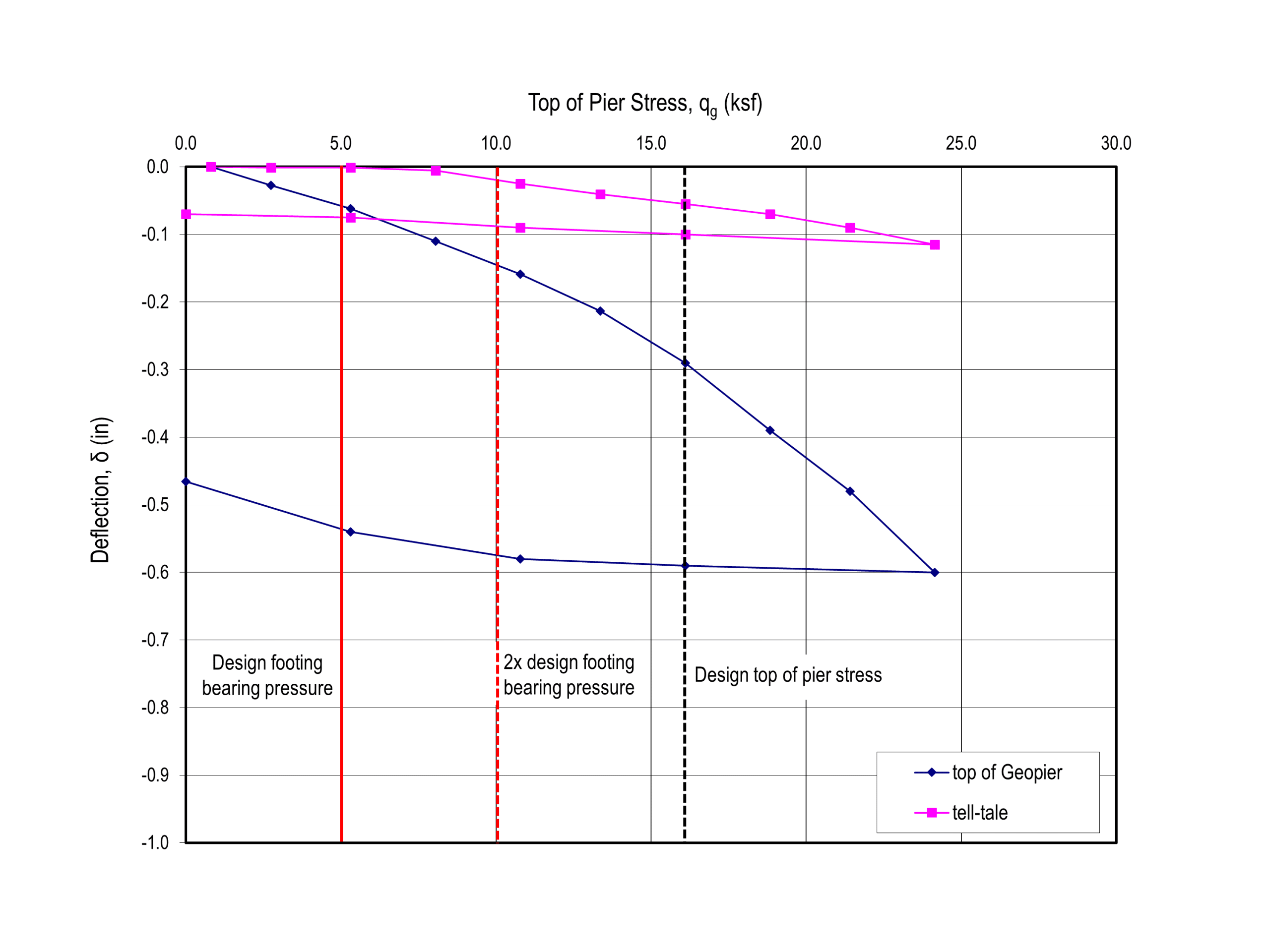
Figure 2 – Example Modulus Load Test Results (Source: Geopier Foundation Company Technical Bulletin 12)
In summary, field modulus testing should be a function of design top-of-pier stress and should be run to a maximum load of 150% of that stress, not design footing bearing pressure, to help demonstrate that the aggregate pier will exhibit a safe response during service loading. For further detail on proper AP modulus/load testing procedures, please refer to GFC Technical Bulletin 12 or feel free to reach out to us to discuss further.