Drilled Micropiles Support New Bridge in Connecticut
Introduction:
The Connecticut Department of Transportation (DOT) needed to replace a single-span bridge along the Route 110 Corridor leading into downtown Stratford, Connecticut. The project was broken into two phases, ensuring that half of the bridge would remain open to traffic at all times. The first phase of work focused on the southbound side, and once complete, work transitioned to the northbound side.
Soil Conditions and Drilled Micropile Performance Requirements:
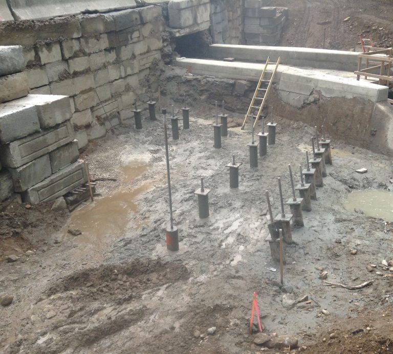
Subsurface soil conditions consisted of approximately 5 to 15 feet of sand overlying sloping bedrock. Due to relatively high vertical and lateral loads, the DOT required that the bridge abutments be supported on a total of 60 drilled micropiles (DMPs), 21 of which were designed as battered piles to resist lateral loads. The DMPs had a design capacity of 163 kips. Given the shallow depth to bedrock, the DMPs were designed to derive their capacity via bedrock sockets (“rock sockets”).
Project Challenges:
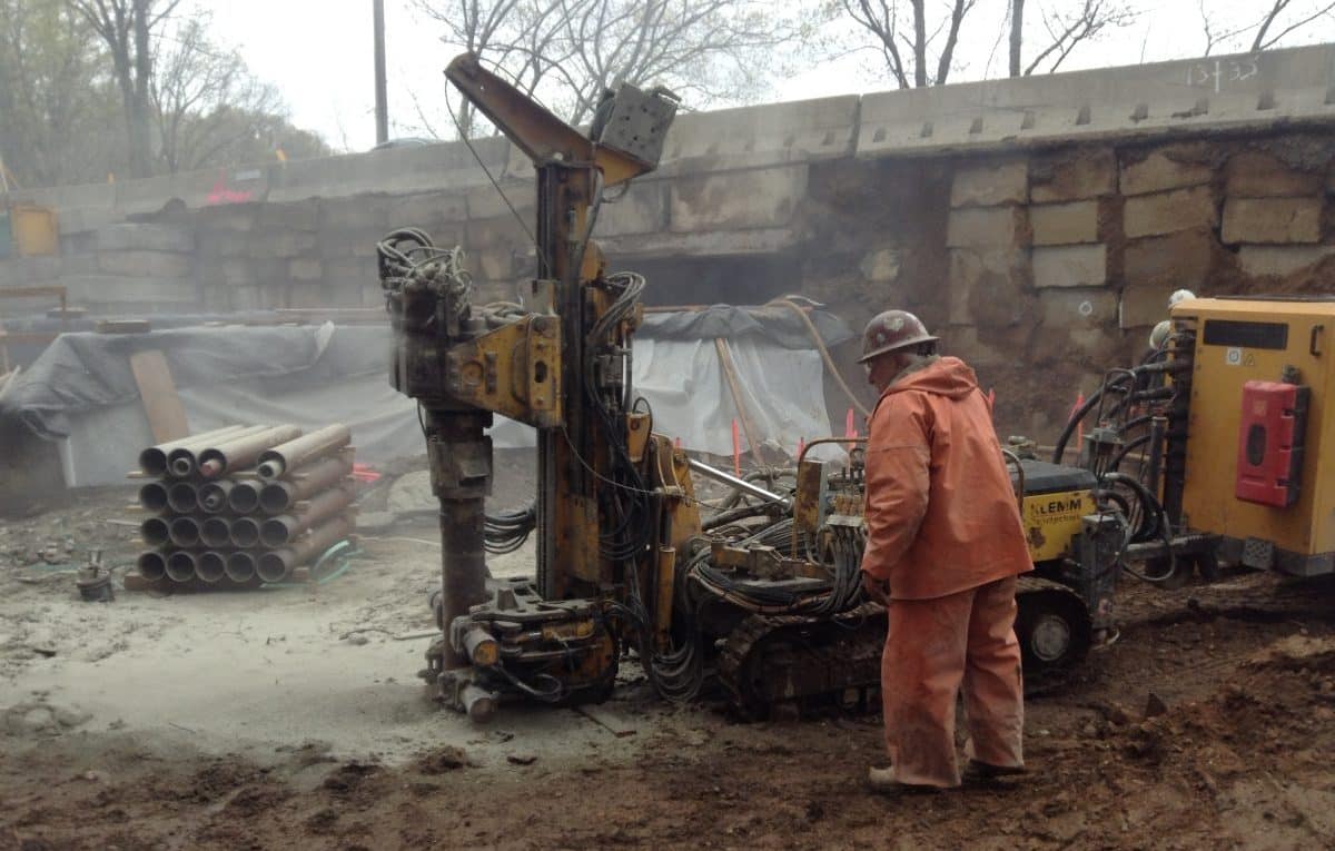
DMP installation needed to occur from within a depressed open-cut excavation such that the working subgrade was near the top-of-pile design elevation. Working within an excavated area while the other half of the roadway remained open created relatively tight (but manageable!) working conditions for the crew. For the second phase of work, the piles were installed around a live gas main. Working around the gas main required careful coordination and precise construction methods to ensure safe working conditions and uninterrupted gas service. Furthermore, the Freeman Brook was as close as ten feet to the work area, so potential impacts to the brook had to be managed prudently. The work area was contained using tarps, haybales, and other protective measures. Drilling and grouting spoils were 100 percent contained within small local excavations (“spoil pits”).
Pile Installation:
Helical installed the 60 drilled micropiles per the DOT’s design using compressed air percussive drilling methods. A specialty winged drill bit was used to seat 7-5/8-inch diameter permanent steel casing into bedrock. After seating the casing, our crew drilled an additional 9 feet into the rock with a conventional drill bit to form a 6-inch diameter rock socket bond zone between the grout and surrounding bedrock. The rock sockets and cased hole were then tremie grouted and the threaded core steel was installed down the full length of the pile. Since the bedrock depth varied, final pile lengths ranged from about 12 to 18 feet.
Quality Assurance and Control:
Prior to DMP production work, full-scale load tests were completed on two non-production piles. The test results indicated less than about ½-inch of deflection at 100% design load and confirmed that the DMPs would perform as designed.
Drilled Micropile Advantages:
- Installation within a constrained site
- Helped permit phased construction and maintain traffic over the bridge
- Work was performed safely around an active gas line
- No vibrations or environmental impacts to the surrounding area
- High load carrying capacity for relatively short piles
- Pile lengths were easily adjusted based on varying bedrock depth

