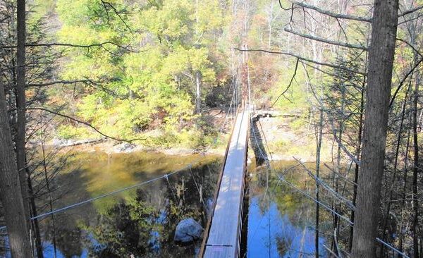
A new pedestrian bridge over the Shepaug River in rural Washington, Connecticut was the focal point of a walkway path upgrade. The design featured a suspension bridge spanning nearly 150 feet, requiring foundations capable of resisting significant compression and tension loads.
The design included vertical compression loads for some of the foundations and high tensile loads for the majority of the foundation structures. The load resistance design was further complicated with angled (non-vertical) tensile loads, requiring special consideration during foundation installation. In addition to the load resistance challenges, mobilization to and working within the environmentally-sensitive remote site required special considerations.
Foundation design was specified as a combination of micropiles and rock anchors. The micropiles were designed for 80 kips in compression, using 8 inch nominal diameter casing and a 6 inch rock socket beyond the casing. A full length #14 Grade 75 threadbar was inserted within neat cement grout to transfer the load to the rock socket. The rock anchors were designed for 60 kips in tension, using 5.5 inch casing to rock and a 4 inch diameter rock socket beyond the steel casing. A #8 high strength Grade 150 threadbar was installed within the neat cement grout for each of these elements.
Helical Drilling’s access to the remote site was accomplished with care by mobilizing to a very small parking area, followed by navigating the equipment up a wooded, dirt walking path to each bridge abutment. Extreme caution while drilling had to be taken due to the complex design and the nature of the site. Once positioned, the challenge of resisting the angled tension loads was addressed by using angled drilling techniques to penetrate the varying depths of overburden soils above the rock and develop the bonded lengths in rock. Specific drilling angles had to be calculated at each location before drilling could commence.
As the primary support for the pedestrian bridge, the designed incorporated double corrosion protected anchors to minimize corrosion and maintain integrity for their design life. Once installed, the anchors were tested and “locked off” to verify superior capacity. The lock-off procedure also created a degree of initial tension to hold the pile caps locked in place to avoid even the most minor amount of “slacking”.